
Hello there my STEAM friends,
Let’s look at some quick foundational things in Autodesk Inventor – what are the different file types that can be created and used with Autodesk Inventor? Just like Microsoft Office has some specific file types for Word documents, Excel spreadsheets, PowerPoint presentations, and Publisher publications, Autodesk Inventor also has specific file.
Inventor uses different types of files to prepare 2D drawings, 3D parts, assembly, and presentation models. Each file type and file itself serves a specific design and documentation purpose.
What are you designing and what file should you use for it?
A basic design may require only a single part file or a part file and drawing file.
Complex projects that include multiple items may require hundreds of part, assembly,
presentation, and drawing files.
Let’s Get Started
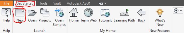
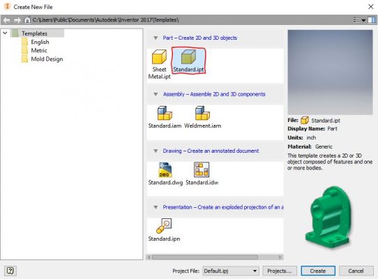
To see the different types of files you can create with Autodesk Inventor, click the New button on the Getting Started tab. You’ll see the New File dialog that looks like this:
4 Main Types of Inventor Files
There are four main categories of Inventor files:
- Part files
- Assembly files
- Drawing files, and
- Presentation files.
Part (.ipt) Files
At the top, there are Part files.
- The file extension “.ipt” stands for “Inventor Part” file.
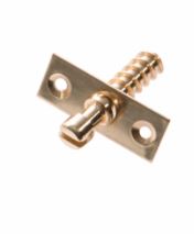
- A part file is a single item. So, for example, you may have single parts like
- a drill bit,
- a single ball bearing in an engine,
- a single slat on the wing of an aeroplane,
- or a tail light of a car.
- In the Part environment, you can see Standard.ipt. Select that – you will now see what this type of file can be used to create. Again, remember during design that part files represent single items in a design.
- Single body parts can then be included in assemblies to make a whole design made up of multiple part files.
- All parts start with a sketch. A sketch is the profile of a feature and any geometry (such as a sweep path or axis of rotation) required to create the feature.
- Part files are then referenced into assembly files as parts for assemblies, and into drawing files to create 2D part drawings.
Assembly (.iam) Files
- The file extension “.iam” stands for “Inventor Assembly” files.
- These files are used to create assemblies, or sub-assemblies (assembled separately but meant to be part of a large design).
- Part files and sub-assemblies are referenced into an assembly to build large machines or components. <<screenshot>>
- Assembly files can themselves be referenced into
- other assembly files as sub-assemblies,
- presentation files, and
- drawing files.
- Assembly constraints are used then to define the relative position these parts or sub-assemblies can occupy with respect to each other. An example is a single screw fitting into a latch.
6. You can insert parts into an assembly or use sketch and part commands to create parts in the context of an assembly.
The assembly browser is a convenient way to activate components you want to edit. Use the browser to edit sketches, features, and constraints, turn component visibility on and off, and do other tasks. In the following image of an assembly, two of the components display an icon indicating they are part of a contact set. Components that belong to a contact set behave as they would in the physical world.
Drawing (.idw, .dwg) Files
After you create a model, you can create a drawing to document your design. In a drawing, you place views of a model on one or more drawing sheets. Then you add dimensions and other drawing annotations to document the model.
A drawing that documents an assembly can contain an automated parts list and item balloons in addition to the required views.
The templates to use as the starting point for your drawings have the standard drawing file extension (.idw, .dwg).
Autodesk Inventor maintains links between components and drawings, so you can create a drawing at any time during the creation of a component. By default, the drawing updates automatically when you edit the component. However, it is a good idea to wait until a component design is nearly complete before you create a drawing. Edit the drawing details (to add or delete dimensions or views, or to change the locations of notes and balloons) to reflect the revisions.
Presentation (.ipn) Files
Presentation files are a multi-purpose file type. Use a presentation file to:
- Create an exploded view of an assembly to use in a drawing file.
- Create an animation which shows the step by step assembly order. The animation can contain view changes and the visibility state of components at each step in the assembly process. You can save the animation to a .wmv or .avi file format.
- An Interview with the Co-Founders of Dermanostix - August 14, 2020
- NASA & SpaceX’s Successful Space Launch - June 12, 2020
- Types of Engineering - June 10, 2020